
The motorcycle wiring harness: role, faults, diagnosis and repair
Wires, connectors, grounds: the wiring harness links everything electrical on your bike. Its role, construction, faults, diagnosis and repair explained.
An indicator that goes out when you turn the handlebars. A dashboard that flickers over cobbles. A bike that dies in the rain, then runs as if nothing happened once it has dried out. In most of these cases the starter, the battery or the ECU are not to blame: the culprit is often a chafed wire, a corroded connector or a loose ground. In other words, the wiring harness.
You rarely see it, hidden under the tank, the seat and the bodywork, yet everything electrical on your bike goes through it. Here is how it is designed and built, why it gets damaged, how to recognise and diagnose a fault, and what you can reasonably repair yourself.
What is a motorcycle wiring harness?
Definition
A wiring harness (or wiring loom) is a set of electrical wires grouped together, protected and terminated with connectors. It is designed for one specific model: every wire has a predefined length, cross-section, colour and route, and every branch ends exactly where the component it feeds is located.
The harness produces no energy and makes no decisions. Its job is to connect: the battery to the loads, the controls to the equipment they operate, the sensors to the control units. It is the bike’s “nervous system”, while the ECU is its brain and the battery its heart.
Main harness and sub-harnesses
On most motorcycles you will find:
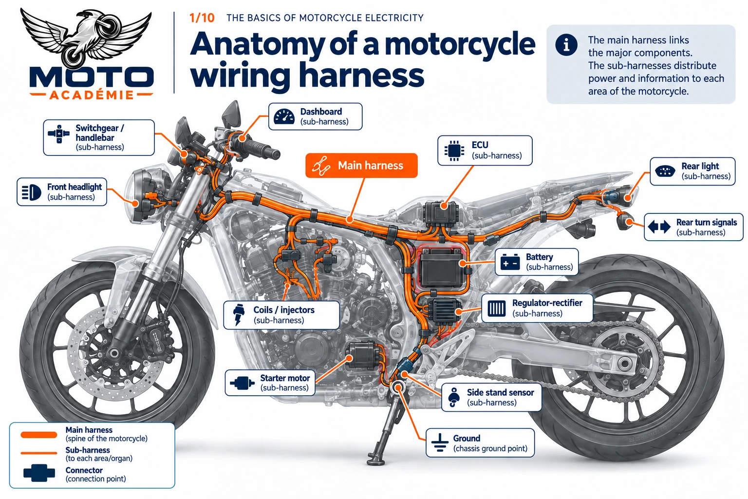
- The main harness: the backbone of the system. It runs along the frame, usually under the tank, from the front (headlight area, dashboard, switchgear) to the rear (tail light, indicators, number-plate light). It links the battery, the fuse box, the relays, the engine ECU and the ignition switch.
- Sub-harnesses: shorter sections plugged into the main harness by connectors. Typical examples: the rear lighting harness, the handlebar switchgear harness, the dashboard harness, or the engine harness feeding injectors, coils and sensors.
This split makes production, factory assembly and repair easier: a tail-light sub-harness damaged in a crash can be replaced without touching the main harness.
Its place in the electrical architecture
It is important to separate the harness from the equipment it connects:
- Power sources: battery, alternator (stator), regulator/rectifier.
- Control and protection devices: ignition switch, switchgear, fuses, relays.
- Control units: engine management ECU, ABS unit, dashboard, and on recent bikes a body control module, an inertial measurement unit (IMU), etc.
- Sensors and actuators: speed sensors, throttle position sensor, temperature sensors, lambda sensor, injectors, coils, starter motor, lights.
The harness itself is made up of the wires, their insulation, the sleeving, the connectors, the terminals, the splices (internal junctions) and the ground points. When an indicator stops working, the question is whether the bulb or the flasher unit (equipment) or the wire and its connector (harness) is at fault. That distinction drives the whole diagnosis.
What does the wiring harness do?
Distributing power
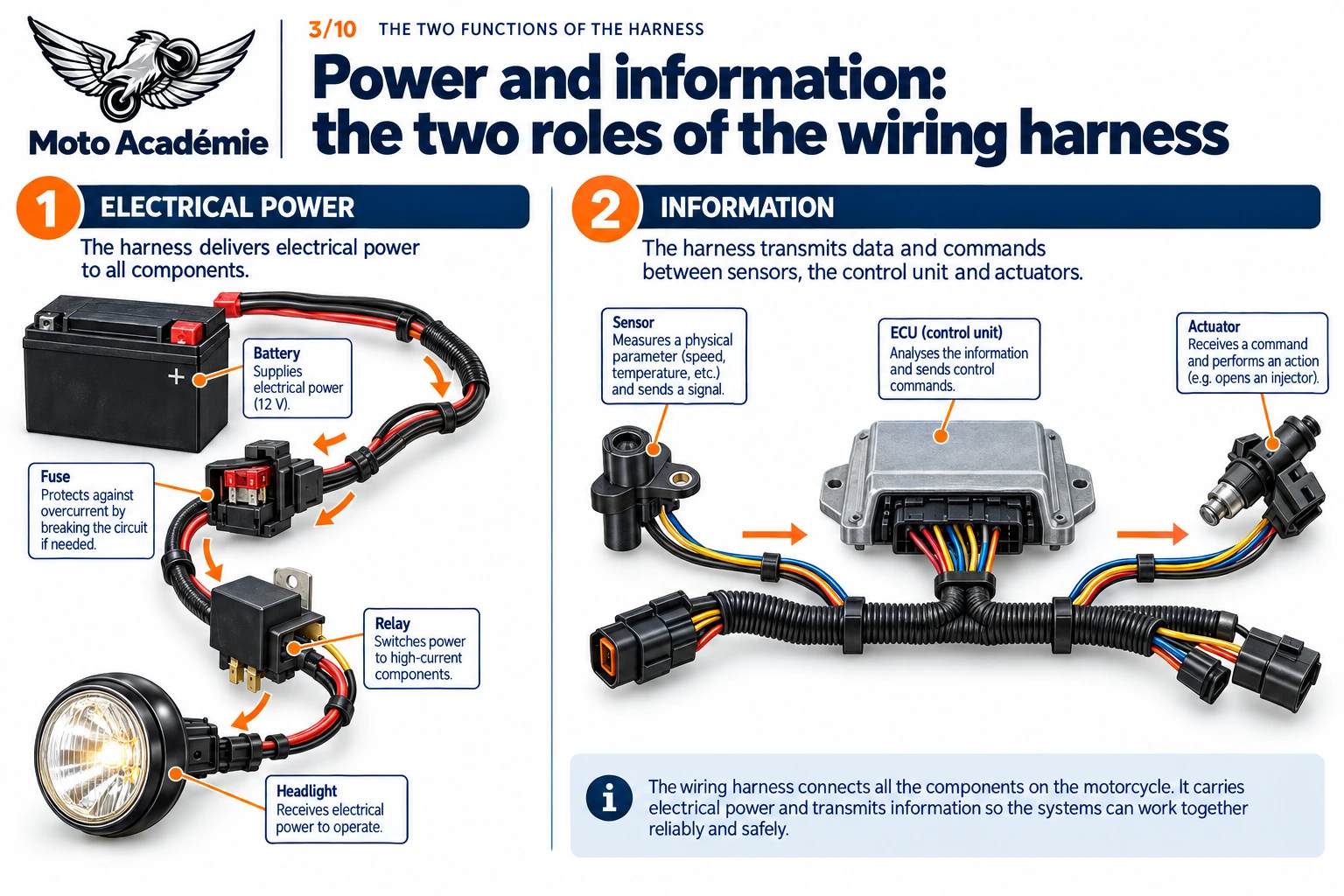
Its first task is to carry current from the battery and alternator to every load with as little loss as possible. The starter motor draws several tens, even over a hundred amps for a few seconds, while a sensor needs only a few milliamps. The harness therefore uses conductors of very different sizes.
Carrying information
Its second, increasingly important task is to carry signals. A crank sensor sends an AC voltage to the ECU, a temperature sensor a variable voltage, a switch a simple open or closed contact. These signals are weak: a stray resistance of a few ohms in a corroded connector is enough to distort a reading, whereas it would go unnoticed on a lighting circuit.
Which functions depend on it?
Practically all of them:
- Starting: starter relay control circuit, side-stand and clutch safety switches, then the heavy cable to the starter motor.
- Ignition and fuel injection: power to the ECU, coils and injectors, and signals back from the sensors (engine speed, throttle position, intake pressure and temperature, engine temperature, lambda sensor).
- Charging: the link between stator, regulator/rectifier and battery, which carries most of the current the bike generates.
- Lighting and signalling: headlights, lights, indicators, horn.
- Safety: ABS wheel-speed sensors, brake-light switches, kill switch, tip-over sensor that cuts the engine in a crash.
Evolving with motorcycle electronics
On a 1970s carburettor bike, the harness was limited to ignition, charging, lighting and a few warning lights. Fuel injection added an ECU, sensors and actuators. Then came ABS, traction control, riding modes, ride-by-wire throttles, cruise control, connected TFT screens, heated grips and IMUs. Since Euro 4 and then Euro 5, EU Regulation No 168/2013 has also required new motorcycles to carry on-board diagnostics (OBD) that store fault codes.
Every new function means more wires. To keep harnesses manageable, manufacturers adopted multiplexing (see below).
What is a wiring harness made of?
The conductors
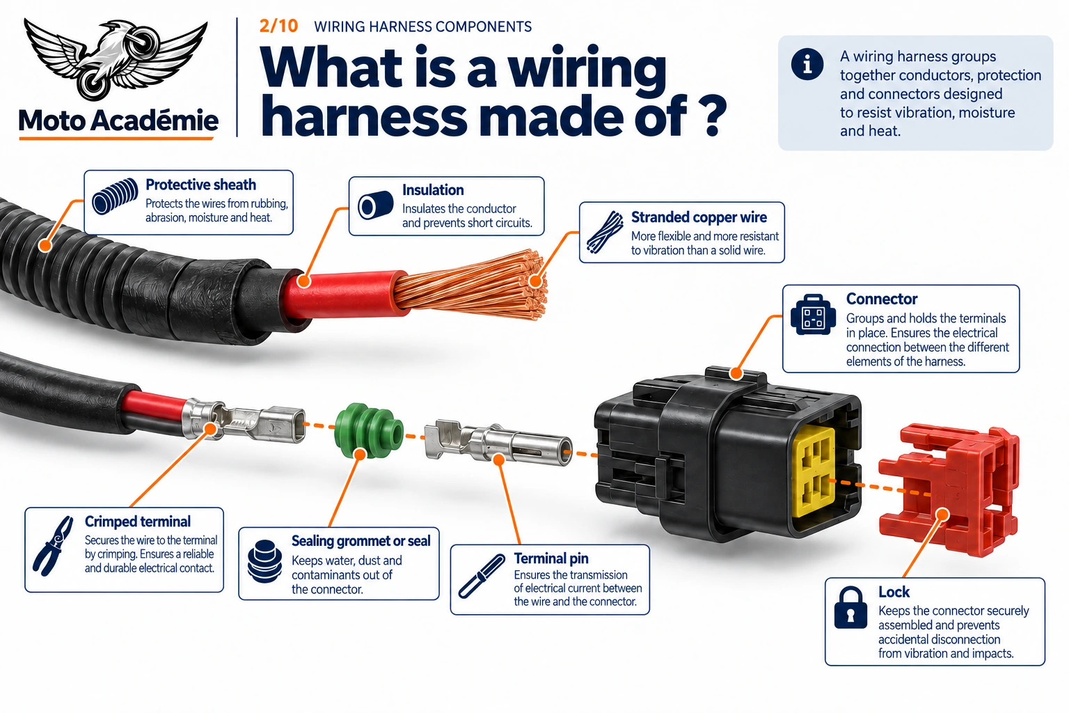
- The core: copper, almost always stranded (many thin twisted strands). Stranded wire withstands bending and vibration far better than solid single-core wire.
- The cross-section: expressed in mm² (or AWG on US diagrams). It is chosen according to the current to be carried and the length. It ranges from a few tenths of a mm² for sensor signals to several mm² for battery and starter cables.
- The insulation: often PVC, or more heat-resistant materials (such as cross-linked polyethylene) near the engine and exhaust. ISO 6722, the standard for low-voltage automotive cables, defines temperature classes from 85 °C (class A) to 250 °C (class H). In Japan, JASO D611 plays a similar role for thin-wall cables (AVS, AVSS, CAVS types).
- Colours: each wire has a base colour and often a tracer stripe (a “green/yellow” wire, for example). There is no universal code between manufacturers: green is ground on many Hondas, while other brands use black or brown. Only the model’s wiring diagram is authoritative.
Sleeving, tape and protection
The wires are bundled and protected by:
- textile or PVC tape wrapped around the harness;
- corrugated conduit (split or unsplit), which resists abrasion well;
- braided sleeving or heat-shrink tubing in certain places;
- rubber grommets and moulded guards at critical points (passing through the frame, contact with the tank);
- ties, clips and clamps that hold the harness to the frame along a defined route.
Connectors, terminals, pins and splices
- Connectors: plastic housings that hold several contacts. On modern bikes most are sealed: each wire passes through its own silicone seal and a perimeter seal closes the housing. A locking tab prevents accidental disconnection.
- Pins and terminals: the metal parts (brass or copper alloy, often tin-plated) crimped onto the end of each wire, male or female.
- Ring terminals: for bolted connections (ground, battery, starter).
- Splices: internal junctions where several wires meet, hidden under the tape. At the factory they are crimped or ultrasonically welded.
Ground points
On a motorcycle, current returns through ground: the battery negative is connected to the frame and engine, and many components “return” through ground wires bolted to specific points. A ground strap or cable often links engine and frame, because the engine sits on mounts that do not always guarantee good electrical contact. A corroded or loose ground is one of the most common faults.
Fuses, relays and control units
Fuses, relays and ECUs are not strictly part of the harness, but they are closely tied to it:
- The fuse box is often built into the main harness. Fuses protect the wires against overheating in a short circuit: their rating is matched to the cross-section of the conductors they protect.
- Relays let a small control current (through the switchgear, for example) switch a large current (starter, headlight, fuel pump), which spares the switch contacts and allows thinner control wires.
- Control units plug into the harness through multi-pin connectors with dozens of contacts.
Multiplexing and CAN bus
Instead of running one wire per piece of information, modern bikes have their control units talk over a data bus, usually a CAN bus (Controller Area Network, standardised as ISO 11898). Two wires twisted together (CAN-High and CAN-Low) carry digital messages shared by all the units: engine speed, wheel speeds, lean angle, control positions. The bus is closed at each end by a 120-ohm termination resistor.

BMW Motorrad was a pioneer: in 2004, with the R 1200 GS, it introduced its “Single-Wire-System”, a multiplexed CAN-bus on-board network that reduced the number of cables and did away with conventional fuses, replaced by a central electronic unit that shuts down the affected function in a short circuit (BMW Motorrad press kit, 2004).
Multiplexing makes the harness lighter, but it makes some jobs trickier: a bus fault can cause symptoms on several components at once, and a badly wired accessory can disrupt the whole network.
How is a wiring harness designed and built?
From wiring diagram to harness drawing
Everything starts with the wiring diagram: a list of all the components, the connections between them, the protection (fuses, relays) and the ground points. Engineers then move to the harness layout, in three dimensions, using the bike’s digital model: where each branch runs, where the mounting points are, what lengths are needed.
Wire sizes and routing
For each wire, the cross-section must be chosen. It depends on the current, the length (voltage drop increases with length), the ambient temperature and the fuse protecting it. Routing is a puzzle specific to motorcycles: the harness must avoid the exhaust and cylinder heads, not be pinched by the tank or seat, and remain accessible for maintenance, all in a very tight space.
Cutting, crimping and assembly
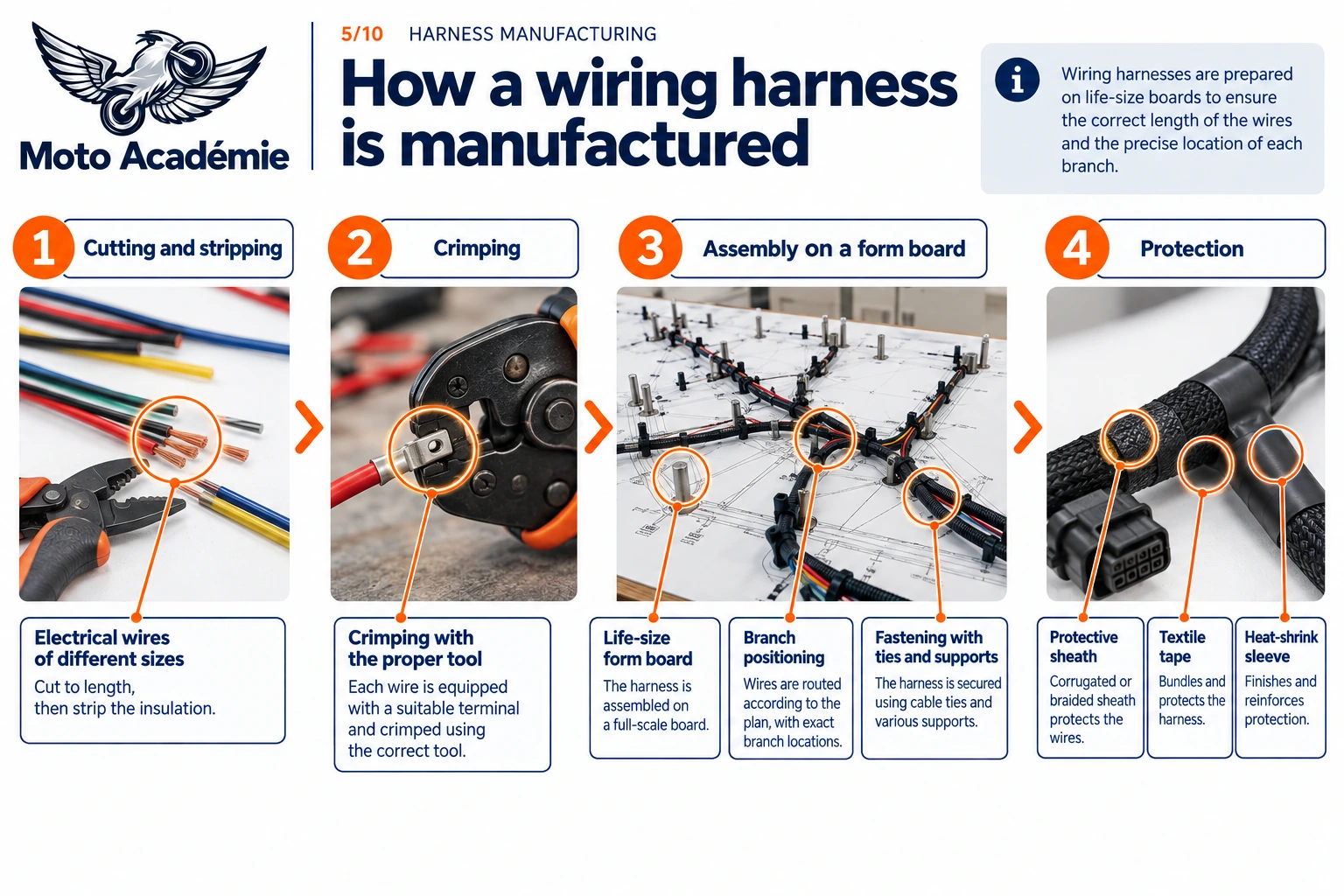
At the factory, cut-strip-crimp machines (from makers such as Komax or Schleuniger) cut each wire to length, strip its ends and crimp the terminals automatically. Crimping means deforming the terminal around the conductor to create a gas-tight mechanical and electrical joint, without solder. Crimp height is checked, because a crimp that is too loose or too tight will fail later.
The assembly itself is done on a formboard, a full-size jig where supports mark out the route of each branch. Operators lay the wires one by one, insert the terminals into the connectors, make the splices, then tape up and fit sleeves and ties.
Still largely manual
This assembly stage remains largely manual, even at the big suppliers (Yazaki, Sumitomo Electric, Furukawa, Aptiv, etc.). Because wires are flexible, robots struggle to handle them, thread them through sleeves and tape the branch-outs. That is why harness production is often located in countries with moderate labour costs.
Quality control and electrical testing
Every finished harness goes onto a test bench: all its connectors are plugged into test connectors, and an automated tester checks that every connection exists (continuity), that no wire touches another (no short circuit) and that every pin is in its proper place. Pin insertion and locking and visual appearance are also checked, and crimp height and pull-out strength are sampled.
Constraints specific to motorcycles
A motorcycle harness faces harsher conditions than a car’s:
- Vibration: singles and twins transmit significant vibration to the frame. Every stiff point (taut wire, rigid splice) becomes a potential break point.
- Heat: the harness runs close to the engine, sometimes above exhaust headers.
- Water: rain, wheel spray, washing. Nothing is sheltered the way it is under a car bonnet.
- Packaging: little space, many functions and tight bend radii.
- Handlebar movement: switchgear and dashboard wires flex every time you steer, thousands of times a year. The harness needs enough slack to go from lock to lock without tension, but not so much that it gets pinched. Workshop manuals devote an entire section to cable and harness routing.
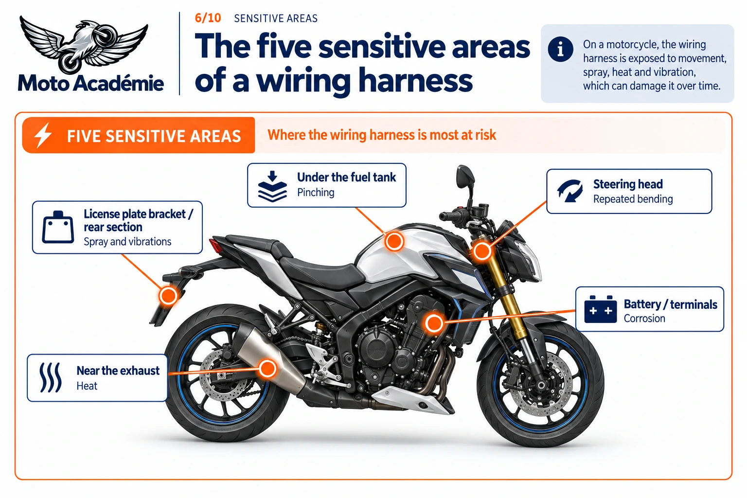
Why does a wiring harness fail?
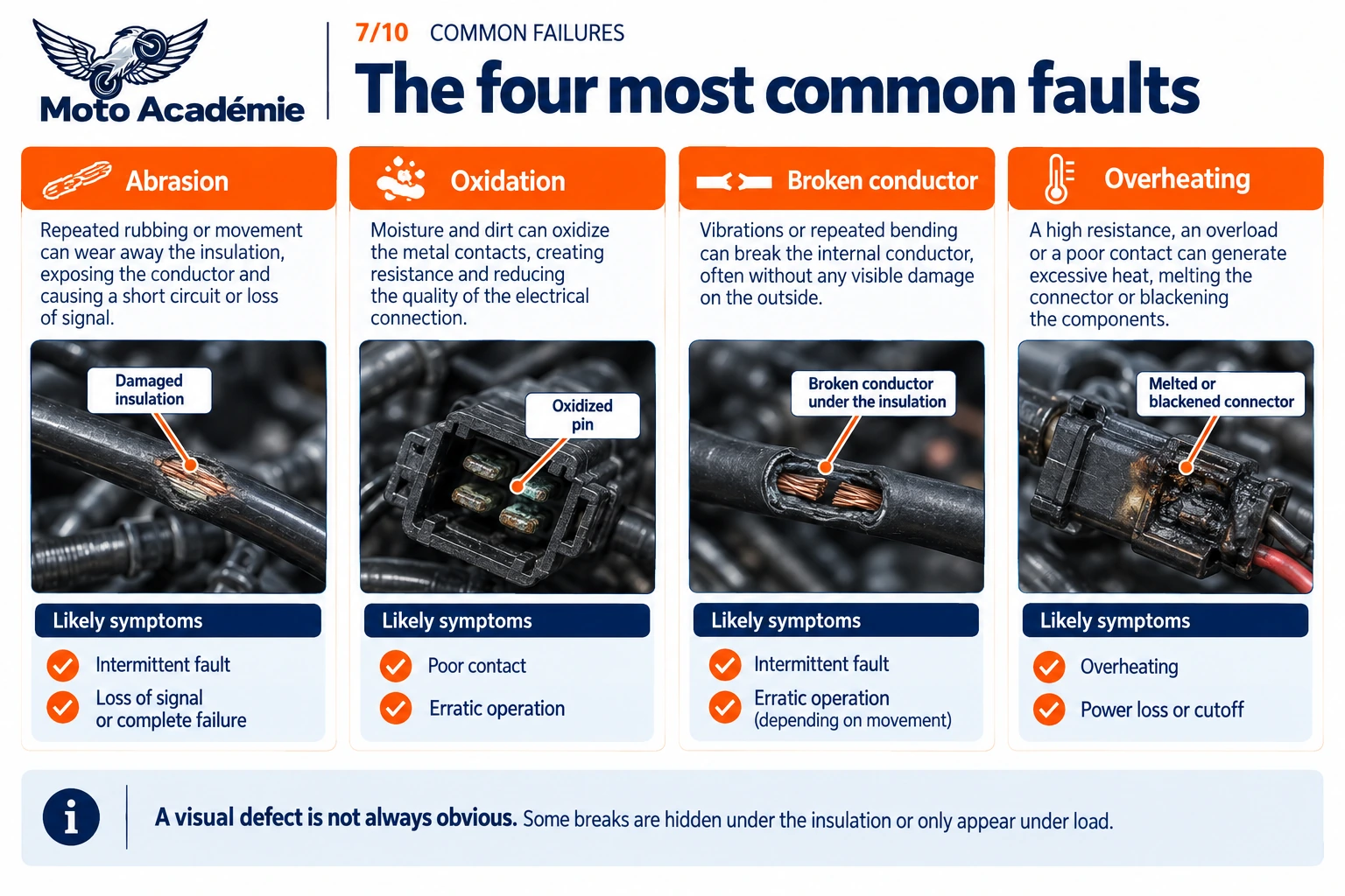
Chafing against the frame or engine
This is the best-documented cause. Under vibration, a harness touching a metal edge wears through its tape, its sleeve and then the wire insulation. The bare conductor then touches ground. Several official recalls show this:
- Suzuki DL1000 V-Strom 2014-2016 (NHTSA recall 15V-851): the harness could rub against the underside of the fuel tank. Vibration wore the insulation through to a short circuit, with a risk of engine stall.
- Harley-Davidson Street Glide and Road Glide 2024 (NHTSA recall 24V-672, about 41,600 bikes): the red regulator output wire could rub against the front corner of the crankcase. A short to ground blew the 60 A main fuse, cutting propulsion and all electrical power without warning.
- KTM 1290 Super Duke R 2020-2022 (NHTSA recall 21V-122 for the rear harness of 2020 models, then KTM bulletin KTB2211 for the main harness): incorrect routing and missing protection could damage the harness where it contacts the frame, with a risk of short circuit and stalling.
Vibration, flexing and internal breaks
A wire bent thousands of times at the same spot eventually breaks inside its insulation, strand by strand. From the outside, nothing shows. Exposed areas: where the switchgear wires leave the handlebar, around the steering head, the rear light connections on number-plate holders, and where wires leave connectors and are stiffened.
Moisture, corrosion and oxidation
Water getting into a connector (damaged seal, unsealed connector, pressure washing) corrodes the contacts. It can also wick up the wire between the strands and blacken the copper over several centimetres. Road salt greatly accelerates this corrosion.
There is also a “dry” form of corrosion, fretting: under vibration, two contacts rub against each other by a few microns, wearing their plating and producing insulating oxide debris. Contact resistance gradually rises.
Overheating, overcurrent and short circuits
A contact with abnormal resistance heats up in proportion to the current flowing through it. On high-current circuits, such as the alternator-to-regulator link, the heat can melt the connector. Triumph recalled Bonneville, Street Twin, Scrambler and other Modern Classics built between 2021 and 2023 (NHTSA recalls 24V-785 then 26V-078): a combination of oil, temperature, connector fretting and high current raised the resistance of the alternator-to-regulator connector, with cases of scorched connectors and smoke. The remedy replaces the connector with in-line crimped joints.
Loose, damaged or misconnected connectors
A connector with a broken locking tab can partly disconnect. A pin not fully seated in its housing (after a repair, for example) backs out when the connector is mated, and makes poor contact. A female terminal spread open by an oversized multimeter probe no longer grips the male pin.
Ageing materials
Over the years and through heat cycles, insulation hardens and cracks, seals lose their flexibility, tape comes loose. On a bike thirty or forty years old, an original harness can be fragile even without visible damage.
Modifications and poor repairs
This is a major cause on used bikes:
- accessories (auxiliary lights, USB sockets, GPS, alarms, heated grips) connected with insulation-displacement tap connectors that cut into the wires and let water in;
- wires twisted together and wrapped in insulating tape;
- poorly connected LED indicators or aftermarket tail lights;
- fuses replaced with a higher rating, leaving the wire to overheat without protection.
Crashes, accidents and rodents
A crash can crush a connector, tear out an indicator sub-harness or trap wires between fairing and frame. During winter storage in a garage or barn, rodents can also chew through sleeves and wires.
What faults can a damaged harness cause?
Bike won’t start or stalls
If the ECU, fuel pump, coils or starter relay lose their power or ground, the engine won’t start or will cut out. A harness that chafes through to a short also blows the main fuse, cutting everything, as in the recalls above. The typical scenario: the bike stalls on the move, won’t restart, then starts normally half an hour later for no obvious reason.
Intermittent cut-outs
This is the signature of a failing harness. The fault only appears over bumps, at a certain steering angle, after a shower or when the engine is hot (expansion opens or closes a poor contact). In the workshop, at a standstill, everything works.
Lighting, indicators and dashboard
A headlight that dims, an indicator that flashes too fast or stops working, a dashboard that switches off or reboots: these faults often come from a weak ground or power feed. On multiplexed bikes, a CAN-bus fault can trigger error messages on several functions at once.
Charging problems
A battery that drains, an abnormal charging voltage, a battery warning light: before condemning the regulator or the stator, check the connectors and wires linking them. Resistance in a connector distorts the voltage the regulator “sees” and makes the link heat up.
Injection, ignition, sensors, warning lights and fault codes
A sensor with a broken wire or a corroded connector sends a wrong value or nothing at all. The ECU then lights the engine warning lamp and stores a fault code, or switches to limp mode (unstable idle, hesitation, limited revs). The code tells you which circuit has a problem, not which part has failed.
Fuses that keep blowing
A fuse that blows repeatedly almost always points to a wire touching ground somewhere (chafing, pinching) or a badly wired accessory. Replacing it with a higher rating turns the problem into a fire risk: the wire will heat up until its insulation melts.
Overheating and short circuits
A smell of hot plastic, a deformed or browned connector, softened insulation: these signs mean the bike must be stopped. A dead short on an unprotected circuit can start a fire.
Why these faults are hard to pin down
A failing harness mimics a component failure. A throttle position sensor with a corroded connector produces exactly the same symptoms as a faulty sensor. A regulator with a poor feed looks dead. That is why riders regularly replace the battery, the regulator, then sensors, to no avail, when the fault was a connector worth a few euros. Intermittency adds to the difficulty: a fault that doesn’t show up during testing can’t be measured.
How to diagnose a wiring harness problem
1. Record the symptoms and circumstances
Before taking anything apart, describe the fault precisely: when does it happen (cold, hot, in the rain, after washing)? Under what conditions (over bumps, when steering, at high revs)? Which components are affected? If several unrelated functions fail together, look for what they share: a fuse, a ground, a connector or a common harness section. If the bike has on-board diagnostics, reading the fault codes (with the right tool) points to the circuit involved.
2. Visual inspection
Remove the seat, tank or panels if needed and follow the harness. Look for sleeving worn where it contacts the frame, missing ties, pinched wires, heat marks, browned connectors, missing seals, green deposits on pins, and any sign of previous work (tap connectors, non-original tape). Added accessories deserve a close look.
3. Fuses and grounds
Check the fuses (a fuse can look fine and still be open). Remove, clean and retighten the main ground points: battery negative terminal, frame mounting, engine-to-frame strap.
4. The wiring diagram
The workshop manual’s diagram is essential. It shows wire colours, pin numbers, intermediate connectors and splices. It tells you which components share a power feed or a ground, and therefore where to look.
5. Multimeter measurements
- Voltage: check that a component receives battery voltage at its connector with the ignition on.
- Continuity and resistance: with the battery disconnected, measure a wire’s resistance end to end. It should be close to 0 ohms. Also check there is no continuity between that wire and ground or a neighbouring wire, which would indicate a short.
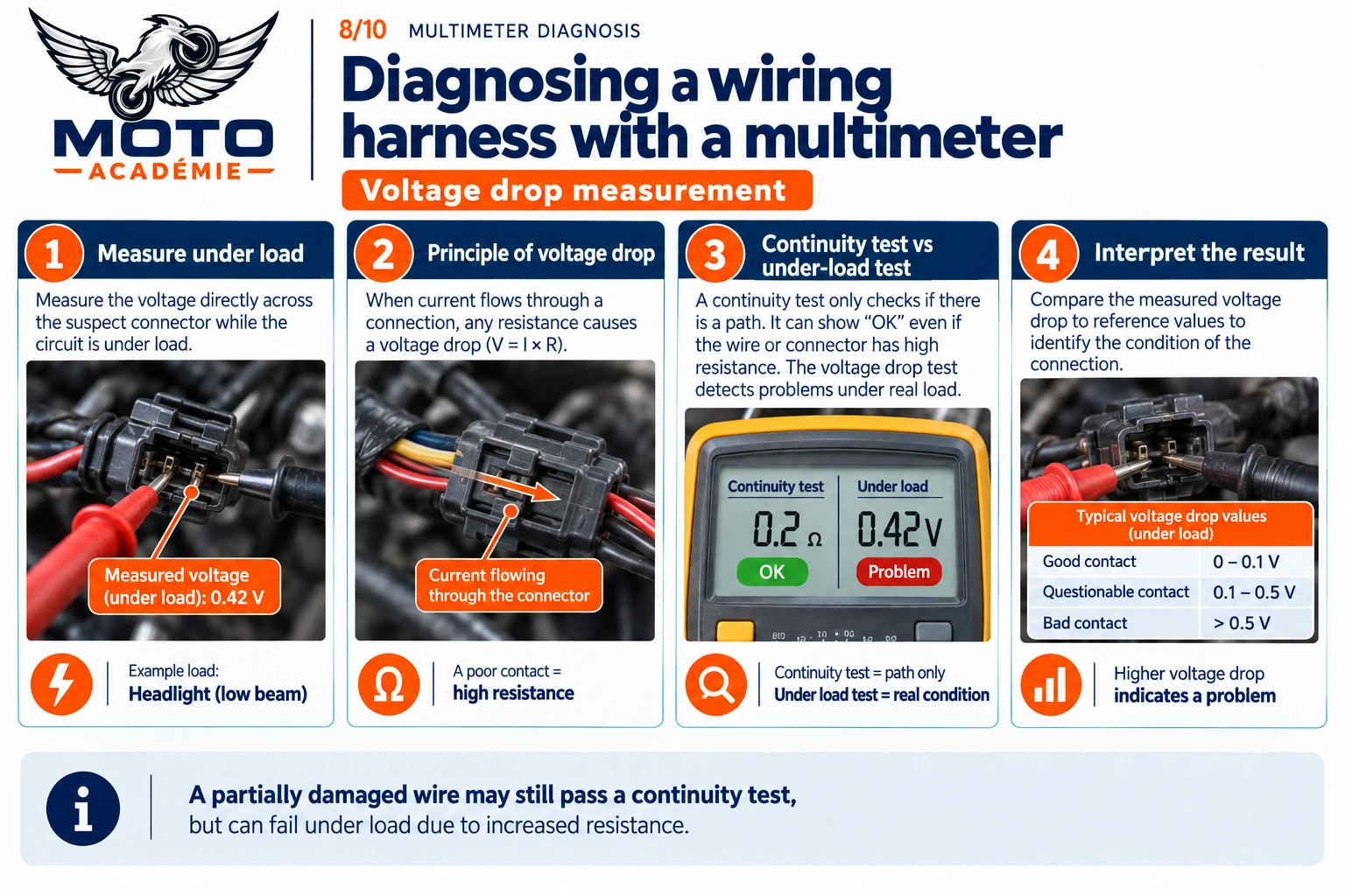
- Voltage drop: the most revealing test. With the circuit under load (headlight on, starter cranking), measure the voltage across a wire, a connector or a ground. A healthy circuit loses only a few tenths of a volt. As a guide, workshop references often accept around 0.1 V per connection and 0.2 V on a ground circuit, but the figures in your model’s manual take precedence.
Why voltage drop? Because a wire with only a few intact strands left shows perfect continuity on a multimeter (which passes only a tiny current), but collapses as soon as it has to carry several amps.
On a CAN bus, a simple check is to measure the resistance between CAN-High and CAN-Low with the battery disconnected: with the two termination resistors in parallel, you should read about 60 ohms. Around 120 ohms or an open circuit suggests a break in the bus or a missing termination.
6. Hunting intermittent faults
For an intermittent fault, recreate the conditions. With the engine running or ignition on, gently move the harness section by section, turn the bars from lock to lock, tap the connectors, warm an area with a heat gun on a low setting or mist it with a little water, while watching the symptom or the multimeter. When the fault appears, you have found the area.
7. Harness or component?
The logic is simple: if the component receives correct power, ground and signals at its own connector and still doesn’t work, the component is faulty. If what reaches the connector is wrong while the source is fine, the fault lies in between: it is the harness. This method avoids replacing parts at random.
8. Precautions
- Disconnect the battery negative terminal before unplugging connectors or measuring resistance.
- Never unplug an ECU with the ignition on.
- Never measure resistance on a live circuit.
- Don’t force probes into a sealed connector or pierce insulation to take a reading: you let moisture in and can spread the terminals. Use thin back-probe pins or test adapters.
- Don’t bridge pins at random: one wrong pin can destroy an ECU.
- On airbag-equipped bikes (Honda Gold Wing), follow the manufacturer’s procedures strictly.
Does a wiring harness need maintenance?
No periodic maintenance as such
Service schedules generally include no specific harness task: no fixed replacement interval, no product to apply. A well-designed, well-fitted harness can last the life of the bike. That doesn’t mean it should be ignored.
Useful preventive checks
Use routine jobs (battery replacement, tank removal for plugs or air filter, valve clearance checks) to look at:
- sensitive areas: near the steering head, under the tank, around the battery, near the exhaust, around the number-plate holder;
- mountings: ties and clips in place, guards fitted;
- battery terminals and ground points: tight and clean.
Turning the bars from lock to lock while watching lets you check that no wire is stretched or pinched.
Cleaning and protecting connectors
Sealed connectors should only be opened when there is a reason to, since every handling wears seals and locks a little. If there is corrosion, electrical contact cleaner will clean the contacts. Dielectric grease (silicone, non-conductive) protects against moisture: apply a thin film to the seals and housing rather than packing the pins. If the workshop manual specifies a particular product, use that.
Washing, dismantling and mechanical work
- Washing: avoid aiming a pressure washer at connectors, the fuse box, switchgear, dashboard and ECU. High-pressure water gets past seals.
- Dismantling: when removing the tank or a panel, note the harness route (a photo is enough). On reassembly, put every tie back in place and check that no wire is trapped under a screw or panel edge.
- Unplugging: release the locking tab before pulling, and always pull on the housing, never on the wires.
Good practice for fitting electrical accessories
- Use a dedicated power feed: a wire from the battery, protected by a fuse as close as possible to the terminal, and switched by a relay triggered by an ignition-switched circuit.
- Avoid tap connectors and improvised splices on the original harness.
- Check that the alternator can supply the extra load: available output is limited on small-capacity bikes.
- On a multiplexed bike, use the manufacturer’s sockets and interfaces (accessory socket, CAN interface). LED indicators may be detected as blown bulbs by the lamp-monitoring system.
- Secure the new wiring along the original harness with ties, without tension and away from the exhaust.
Can a damaged wiring harness be repaired?
When a local repair is possible
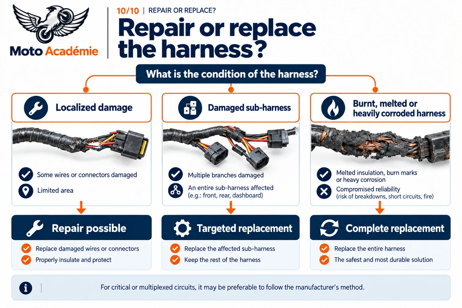
A local repair makes sense when the damage is limited and accessible: a wire cut or chafed over a few centimetres, a corroded terminal, an indicator connector broken in a crash. If the rest of the harness is sound, a good repair is as reliable as the original.
Cut, damaged or corroded wire
Cut the wire either side of the damaged area until you reach bright copper. Copper blackened over a long length shows that corrosion has wicked up the wire: a longer section must then be replaced. Then join in a piece of new wire of the same cross-section. If several neighbouring wires are repaired, stagger the joints so you don’t create a bulge or a stiff point in one place.
Replacing a terminal or connector
Pins are released from the housing with a thin tool that frees their locking tang. A new pin of the same type is crimped onto the wire, then pushed back in until it clicks. You need the exact connector reference (makers such as Sumitomo, Yazaki, JST, etc.) to get the right pins and seals. If in doubt, the manufacturer often sells the connector or the complete sub-harness.
Wire size and materials
- Cross-section: at least equal to the original.
- Wire: stranded, with insulation rated for the temperature of the area (more resistant near the engine).
- Terminals and butt connectors: good quality and matched to the wire size.
- Sleeve: adhesive-lined (dual-wall) heat-shrink, which seals the joint.
Crimping, soldering, insulation: pros and cons
- Crimping: the factory method. It requires a crimping tool matched to the terminal type (ratchet, correct die). A universal stripper-crimper or flat pliers give unpredictable crimps. A good crimp withstands a firm pull.
- Soldering: good conductivity, but solder wicks up between the strands for a few millimetres and stiffens the wire. Under vibration, the wire can break just where this stiff zone ends. If you solder, limit the wicking, support the wire on both sides of the joint and protect it with heat-shrink that supports it. Don’t solder a terminal designed to be crimped.
- Insulation: heat-shrink must overlap the joint generously on both sides. Tape alone is not watertight and eventually comes loose.
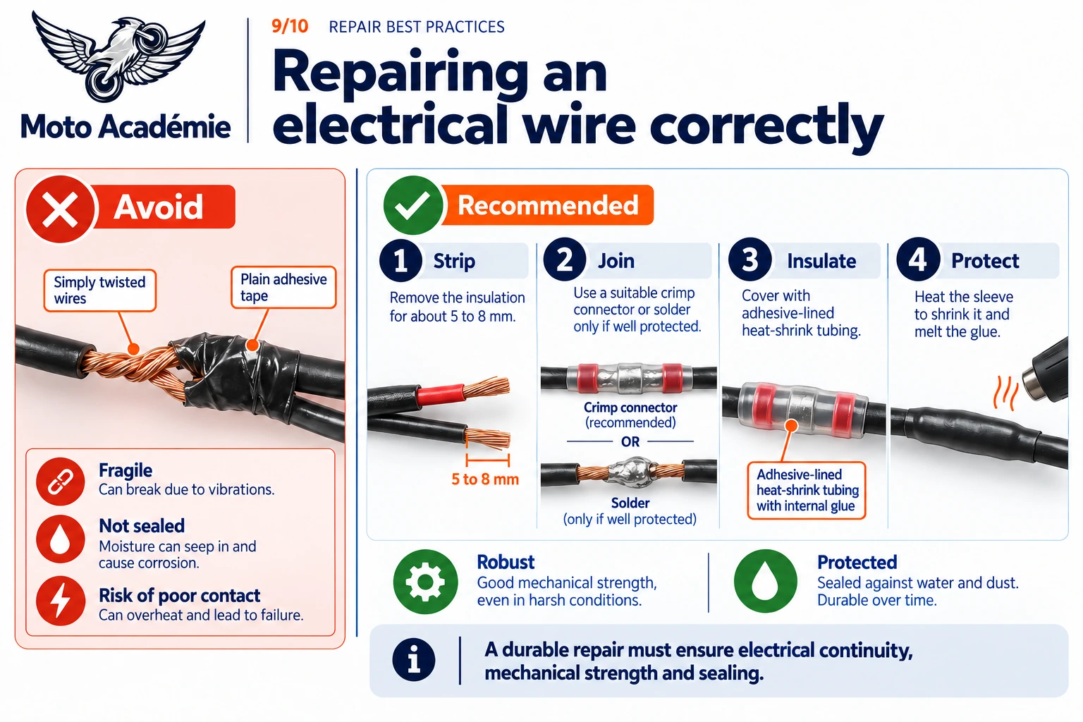
Repair mistakes to avoid
- Twisting wires together and wrapping them in insulating tape.
- Using a thinner wire “because that’s what was to hand”.
- Using tap connectors.
- Leaving a joint unsupported, so it hangs and vibrates.
- Forgetting to refit sleeving and guards at the chafe point: the same fault will return in the same place.
- Fitting a higher-rated fuse to “fix” a problem.
When partial or full replacement is better
Replacement is preferable when:
- damage is extensive or spread along the whole length (wires melted after a short, baked insulation, rodents);
- corrosion has wicked a long way up the wires;
- the insulation is hardened and cracks at the slightest handling (ageing);
- previous repairs have piled up and made the harness unreadable.
Sub-harnesses are often sold separately: there is no need to replace the main harness for a tail light.
Sensitive circuits and the role of a professional
Some circuits don’t tolerate amateur work: CAN bus (both wires must stay twisted, with a minimal untwisted length), ABS wheel-speed sensors, shielded lines, airbag circuits. The manufacturer sometimes imposes a specific procedure, or even harness replacement. A professional with the manufacturer’s diagnostic tool and workshop manual will be quicker and safer in these cases.
Replacing a wiring harness: what are the options?
New OEM, used or aftermarket
- New OEM: guarantees perfect compatibility and approved build quality. It is also the most expensive option, and some part numbers are no longer made for older models.
- Used (breaker’s part): much cheaper, but its real condition is hard to judge. It must come from an identical bike and be inspected along its whole length (sleeving, connectors, signs of heat or repairs).
- Aftermarket or reproduction: common for older bikes. Quality varies: check wire sizes, terminal quality and that colours match the original diagram.
Compatibility
A harness matches a model, a model year and often a specific equipment level: with or without ABS, heated grips or cruise control, European or US version. Two bikes that look identical can have different harnesses. The part number in the manufacturer’s catalogue, looked up from the VIN, is the only reliable way to be sure.
Fitting difficulties
Replacing a main harness is a long job: removing bodywork, tank, often the airbox, and sometimes the battery and control units. Key precautions:
- photograph and mark the old harness route, ties and ground points before removal;
- fit the new one along the same route with the same mountings;
- check full steering lock and that nothing is pinched under the tank or seat;
- on some recent bikes, plan a dealer visit to reset or code certain components.
Repair or replace?
Some criteria to decide:
- Extent of damage: localised damage can be repaired; a harness damaged along its whole length should be replaced.
- Age and overall condition: an old, brittle harness won’t survive repeated work.
- Type of circuit: critical circuits (bus, ABS, ECU power) more often justify replacement.
- Cost: the price of the new part plus labour, weighed against the value of the bike.
Restoring classic bikes
On a classic, the original harness is often forty years old or more: hardened insulation, corroded connectors, layers of repairs. For a serious restoration, a new harness (a reproduction in the original colours) is often the safest option. A restoration is also the time to check the whole system: switches, grounds, regulator condition. Some restorers build their own harness from the original diagram, which takes method, good crimping tools and patience.
Discreet but essential
The wiring harness doesn’t wear like brake pads and appears in no service schedule. Yet it connects every sensor, every control unit and every electrical component on the bike, and a single faulty wire can immobilise a mechanically perfect machine.
Much of the time, electrical faults don’t come from the components themselves but from the connections: a corroded connector, a loose ground, a wire chafed against the frame. Manufacturer recalls show it too: many serious electrical defects come down to how the harness is routed and protected.
Three principles follow. Prevention: a harness that is well secured, protected in the right places and spared the pressure washer and improvised connections lasts a long time. Methodical diagnosis: wiring diagram in hand, a multimeter and voltage-drop tests rather than replacing parts at random. Quality repairs: the right wire size, proper crimping, watertight insulation, and a professional when electronic circuits are involved.